DESIGN EVOLUTION
The evolution of our Kratos ROV design has been characterized by an ongoing pursuit of improved performance, versatility, and efficiency. In Kratos ROV, our focus is on ensuring basic functionality and ruggedness for various tasks. Throughout the competition contribution, advancements in ROV design concepts have led to the adoption of more durable and lightweight materials, resulting in sleeker designs capable of executing all missions effectively. This year, the integration of sophisticated sensors, cameras, and manipulator arms has significantly expanded the capabilities of our ROV, enabling it to undertake a wide range of tasks. Additionally, enhancements in control systems and communication technologies have bolstered the operability of our ROV, enabling more precise and intuitive operation by our team members.
Mechanical Design Process
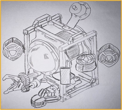
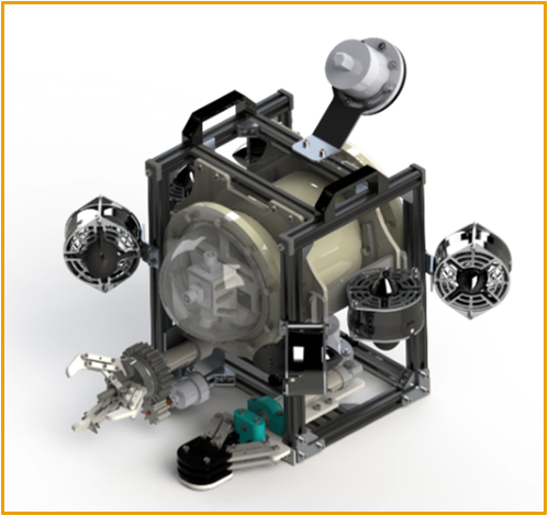
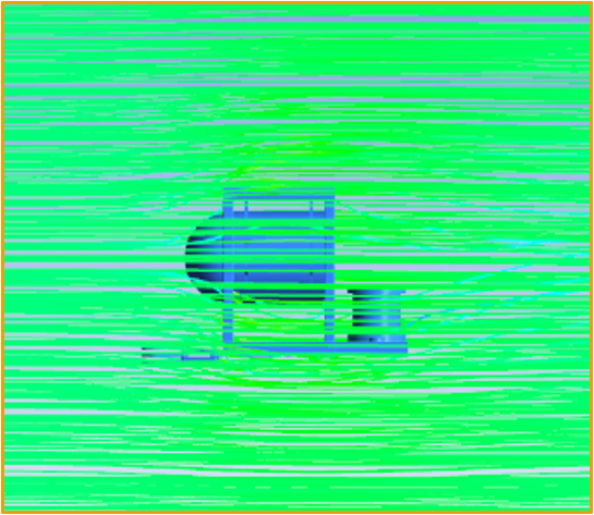
Kratos’s design is completely distinctive. It is based and improves on previously manufactured ROVs. A considerable amount of time has been spent researching the advantages and disadvantages of the previous models, especially the 2022 & 2023 design concepts, as well as thinking about ways in which they could be improved. Following the design team's agreement on the schematics and the creation of freehand sketches-fig (1). The real work began with 3D modeling using SOLIDWORKS -fig (2) as a starting point. We simulated water flow through our vehicle by CFD using ANSYS fluent fig (3). So, we tested our design before Manufacturing. The mechanical design team put in a lot of effort, but their main challenge was getting our vehicle to move smoothly. This was achieved by our streamlined shapes that minimize the drag force on the design. The electrical team incorporated electronic components into our ROV through meticulous planning and close collaboration with the design team. This allowed for responsive control over the ROV's maneuvering path.
Vehicle Structure Approach
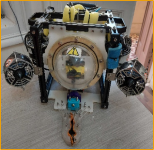
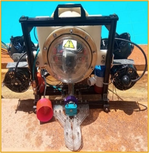
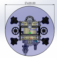
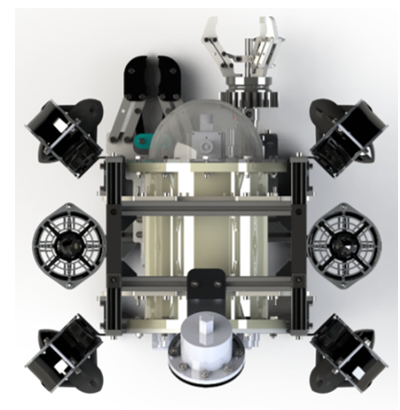
As we mentioned before Kratos ROV is the result of combining the 2022 ROV propulsion system - fig (5), which is represented by six thrusters - with the previous year's frame design - fig (6), where an aluminum extrusion profile is used with an opening design concept of the frame structure that minimizes drag force and reduces eddies in the water. This year's ROVs have more payloads such as two new cameras and a rotational manipulator. Kratos ROV utilizes several innovative design features to retain excellent operational efficiency and control. For size, the main three dimensions of the ROV is 44.4 cm, 42 cm, and 52.6 cm. the vehicle was designed to fit in the launch and return area so it fits in 62 cm of circle diameter -fig (7) which is smaller than the 99 cm -fig (8) that the ROV must pilot through. For weight, The Kratos ROV weighs 11.4 Kg in the air, without a 25-meter Tether weight meeting the competition's weight requirement with the maximum bonus. In freshwater, the Kratos ROV can carry out missions deeper than 10 meters.
Mechanical design Features and Modifications
1. Frame structure approach
There are several tradeoffs of materials, and structure base to be selected So, we selected the best material for the frame structure based on the nature of the component itself and the properties of each material, such as density, impact strength, flexibility, and cost in the following table
| Property | HDPE | Acrylic (PMMA) | Aluminum | PLA | Stainless steel 304 |
|---|---|---|---|---|---|
| Density (g/cm3) | 1 | 1.2 | 2.7 | 1.24 | 8 |
| Impact Strength (J/m) | 260 | 74 | 294 | 96.1 | 325 |
| Flexibility (MPa) | 24 | 71 | 90 | 80 | 540 |
| Cost | Low | Moderate | Moderate | High | Moderate |
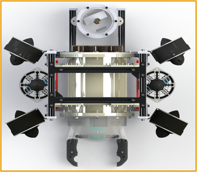
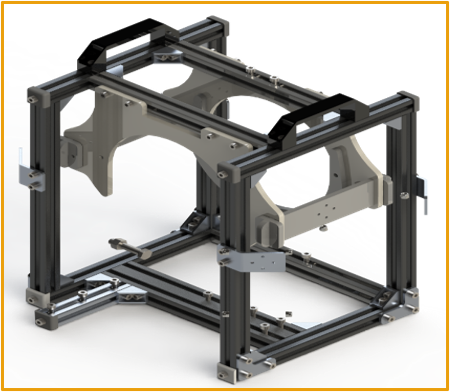
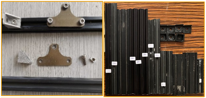
The main structure of the frame -fig (8) consists of 20X20/20X40 Aluminum extrusion profile which is the main innovative decision by the mechanical design team that resulting in higher functionality at reduced cost. The AL-Extrusion profile consists of width of 20/40 mm and a thickness of 20 mm with different lengths. The easy accessibility previewed in the aluminum extrusion accessories such as aluminum corner, aluminum T shape, L shape, T nut and M5X8 bolt -fig (9).
2. Electronics Housing and Its Mounting
Aluminum extrusion profile is inserted to support the enclosure holding parts and to lock the rotation of the enclosure. The holder parts of the enclosure -fig (10) are made of HDPE (High-Density Polyethylene) material that was built using a CNC (Computer Numerical Control) router for its ductility, light weight, and density.
3. Dome
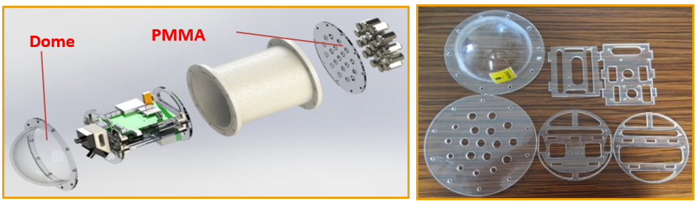
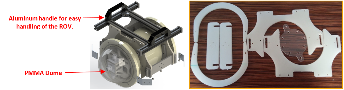
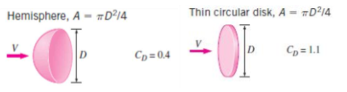
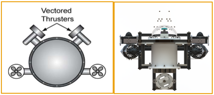
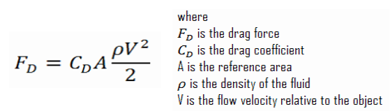
A 6mm thick transparent polymethyl methacrylate (PMMA) dome -fig (11) covers the front face of the ROV. The dome serves various objectives, including providing clear views of the surrounding area to the cameras, offering extra space to accommodate three cameras at different view angles, and lowering the overall drag force on the ROV as its shape is like a half sphere which has a coefficient of drag equal to 0.42-Fig (12) Vs the PMMA Face that its shape is like a circular disc, which has a coefficient of drag equal to 1.1- Fig (12) resulting in more efficient thrust power consumption.
4. Aluminum Handle
For Easy lifting of the ROV we used the most rigid aluminum handles -fig (11) for two sides handling by two of the company members.
5. Sharp Edges Cover
3D printed part -fig (13) of PLA material to cover the sharp edges of the aluminum extrusion profile.
6. Thruster Fixation
Thruster -fig (12) mounts of Stainless steel 304 sheet metal bent are fastened to four of the AL-profiles, two in front and two in back, at a 60/30-degree angle. We preferred the bent stainless steel rather than the 3d printed parts since the stainless-steel material has more strength, and rigidity but the PLA material of the 3d printed parts is fragile and absorbs water that makes it heavier.
7. The manipulator Mounting
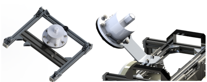
The main manipulator is held in place by a 6mm thick PMMA (Acrylic) base -fig (14) that was built using a CNC (Computer Numerical Control) router and it is fixed on two profiles of 20X20 & 20X40 Aluminum Extrusion -fig (14). The Rotary manipulator is held by sheet metal bent L shaped Aluminum part and fixed into the Aluminum Extrusion by T-nut and M5 bolts.
8. Cameras Mounting
The rear bottom camera enclosure -fig (14) is mounted on a two 20X20 aluminum extrusion profile through T nuts and M5X8 bolts, and the back vision camera is fixed on a sheet metal bent L shaped Aluminum part that is fixed in the aluminum extrusion.
Buoyancy and Stability
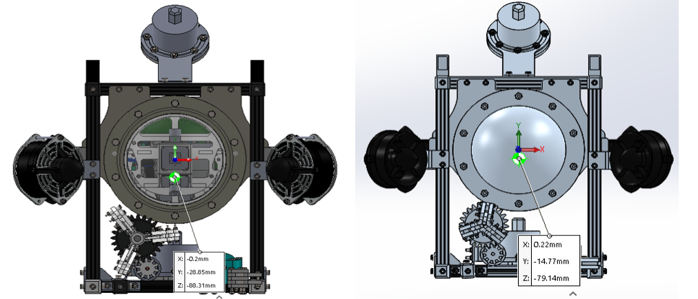
The enclosure on the Kratos ROV displaces the most water, at 6055311.91 cubic centimeters, which is why it was put at the top of the ROV. The center of buoyancy (CB) is shifted upwards fig (15), counterbalancing the entire weight of the ROV and any payloads it may be carrying. The Kratos ROV has a great level of stability because the weights are placed at the bottom. As the foam is added, the result is a somewhat positively buoyant ROV that can be readily canceled out by the vertical thrusters when needed. Because of the symmetrical, the ROV’s CB and CG are centered in the middle of the Kratos ROV and there are reference distance of X, Y, and Z with the origin point of the ROV.
Propulsion
Kratos ROV was designed to maintain all degrees of freedom required for maneuvering. As a first option, we could use two inclined T200 thrusters and two forward T100 thrusters to create a four-thruster configuration. This configuration was used in the 2023 ROV -fig (16), and it reduced power consumption and cost, but the thrust force in all directions was not sufficient to maneuver smoothly. Our second option was to utilize four thrusters T200, which were affordable, consumed more amounts of power, and slightly increased thrust force values, but did not include all degrees of freedom needed.
So, the third option we have chosen is to upgrade the number of thrusters and change the overall configuration which is composed of 6 used T-200 thrusters manufactured by Blue Robotics-fig (17). T-200 thrusters are capable of producing thrust up to 3.55 Kgf in forward operation and 3.00 Kgf in reverse operation. Two Vertical thrusters are placed on the center line of the Kratos ROV symmetrically to provide stability and balance for the ROV while propelling upwards or downwards resulting in the values of the upward and downward thrust forces -Table (2).
The 4 horizontal thrusters are aligned with an angle of 45⁰ providing a variety of maneuvering options in all directions with a good combination of speeds. Forward, backward, right, or left can be performed with 2 thrusters in forward operation during normal speed maneuvering or can be increased by using the 4 thrusters out of which 2 are forward operated and the other 2 reverse operated. The angle 45⁰ was selected to give a good thrust component in the forward, backward, and lateral movement. This alignment of thrusters also enables Kratos Rov to rotate clockwise or anti-clockwise using 2 or 4 thrusters in the same way used for lateral movements. After the first underwater testing, team members found that we needed a higher value of the forward movement than the lateral movement, so finally, we changed the four horizontal thrusters’ angles from 45⁰ to 60⁰ resulting in the values of the forward, and backward maximum thrust forces -Table (2). Alongside this combination of thrusters Kratos ROV, speed can be altered using our control system to give the best suitable speed for any specific mission or task.
| Thrust Force (Kgf / N) | ||
|---|---|---|
| Direction | 45⁰ Angle Orientation | 60⁰ Angle Orientation |
| Upward | 2 x 1.08 = 2.16 Kgf = 21.6 N | 2 x 1.08 = 2.16 Kgf = 21.6 N |
| Downward | 2 x 0.87 = 1.74 Kgf = 17.4 N | 2 x 0.87 = 1.74 Kgf = 17.4 N |
| Forward | 4 x 1.08 x sin (45) = 3.05 Kgf = 30.5 N | 4 x 1.08 x sin (60) = 3.74 Kgf = 37.4 N |
| Backward | 4 x 0.87 x sin (45) = 2.46 Kgf = 24.6 N | 4 x 0.87 x sin (60) = 3.01 Kgf = 30.1 N |
| Lateral | ((2 x 0.87 x cos (45)) + (2 x 1.08 x sin (45)) = 2.76 Kgf = 27.6 N | ((2 x 1.08 x cos (60)) + (2 x 0.87 x cos (60)) = 2.74 Kgf = 27.4 N |
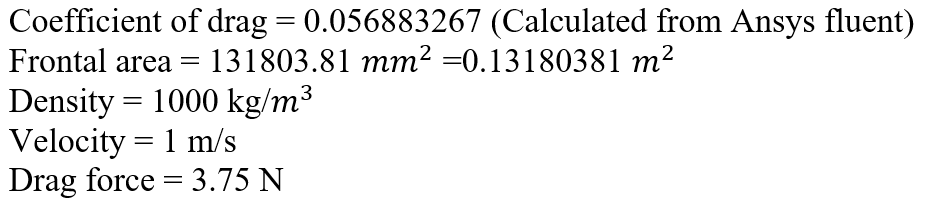
Drag force calculations:
Electrical enclosure and sealing
At the heart of our vehicle is an inclusive lathed machined pressure housing -fig (18) that is secured in place by a pair of rings linked to the top plate, giving it a sleek, hydrodynamic profile. HDPE enclosure with integrated flanges on both sides and 158x2.5 mm O-ring fitted in 1.5 mm deep slots. Because the O-rings -fig (19) are made of Nitrile, they operate as a robust sealant between the enclosure and the faces and were chosen according to Parker's Sealing Handbook specifications.
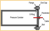
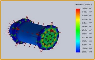
In the enclosure, no chemical sealant was applied. Moreover, the enclosure has a 5mm-thick laser-cut clear PMMA face from one side -fig (20), and a PMMA dome -fig (19) from the other side, which were selected to provide clear vision for the cameras, as well as to check the compression of the O-ring. HDPE material was selected as there are no pores formed within the material, meaning that it can act as a perfectly sealed container. Stress analysis -fig (19) was made by SolidWorks static analysis to ensure that the enclosure can withstand a pressure up to 10 meters underwater with a factor of safety 1.1.